119 Maple Ridge Drive Owners Guide
119 Maple Ridge Drive, Monmouth,
Maine 04259-7334
|
|
Wastewater
(Septic) Plumbing System
Δ Use this symbol to go to the top of the page.
Septic Tank,
Leaching Field, and Ground Level Pump Station
The Wastewater System Flow Diagram
Additional
septic leaching field added in 2010
Two Additional
Sewer Drain Access Points
Special use of The Ground Floor Toilet
1. Location: of System Components
Ground Level
|
1. The ground level bathroom has a
toilet, a wash basin, and a shower. 2. The laundry station has a clothes
washer and a utility sink. 3. All ground level wastewater is
“pumped up” to the gravity flow drain to the 1000-gallon concrete septic
tank. 4. The condensation drain from HVAC
(Heat Pump) air unit above the dining area flows into the ground level pump
station. 5. The Pump Station is located under
the Fresh Water Expansion Tank behind right side removeable access panel
behind the right-side door of the Laundry Station (See photos below). 6. The 1000-gallon Concrete Septic
Tank is located below the front stairs to the Covered Deck. See Septic Tank Access in the Menu. |
First Level
|
1. The first level full bathroom has a
toilet, a wash basin, and a tub / shower. 2. The first level kitchen has a sink
(no food disposal) and dishwasher. 3. All first level wastewater gravity
flows into the septic tank. |
2. Notes / Overview / Description:
The Septic Tank, Leaching Field, and Pump Ground Level Station
|
1. A 1000-gallon concrete Septic Tank
and Concrete Leaching Chambers were installed in 1968 when the home was
built. 2. The original 1968
leaching chambers field was placed on the south side of the home under the
original wooden deck and was 12 X 35 FT for a total of 420 Squar Feet. The
original wooden deck was demolished in 2010 and the ground was excavated down
to the far edge of the concrete leaching chambers away from the home. An
additional eight feet (8 FT) of ground was excavated along the far side of
the existing leaching field and newly washed three-quarter inch (3/4 IN)
stone was placed to the south of the field.
Four-inch (4 IN) perforated schedule forty (40) PVC pipes were
connected to the existing chambers and joined to additional perforated pipes
running parallel East and west of the chambers in two (2) rows and were
covered with a foot more stone and topped off with loom. That procedure added two-hundred eighty
square feet (280 Sq Ft) of leaching field to the existing system, for a total
seven hundred square feet (700 Sq Ft) of leaching field, 3.
Four concrete
gray water leaching tanks were located along the outer South edge of the deck
and used as “foundations” to set the deck post on for a secure base to
support the new waterproof aluminum deck.
The South Side Deck is twelve feet (12 FT) wide and an additional row
of four more tanks is presumed but were not located as the home foundation
was used to support the near side of the deck. 4.
When in 2010 the existing Septic Leaching Chambers were covered with
the “Waterproof” Aluminum Deck it protected the leaching field from ambient
precipitation and improved the dissipation of the “gray water” coming out of
the Septic Tank. The ground under the deck is totally dry and odorless. 5.
The Pump Station was installed in 2010 as a large capacity, heavy
duty sewer pump with an alarm to signal a full tank. The Pump is on the 20
Amp Braker #25 on Main Electric Panel #2. The Alarm is on the 15 Amp Braker
#18 on Main Electric Panel #1. They
are on separate circuits so if the pump trips its breaker the alarm will
still be available to signal a full tank. 6.
See the deck diagram below (not to scale). The blue shaded area represents the added
leaching field. Also See: The Wastewater System Flow Diagram. |
|
|
Deck
Diagram with the amber shaded area representing the original leaching field
which was covered by waterproof deck in 2010. The Blue Shading represents the
additional septic leaching field added in 2010. |
|
|
|
E N House
S W |
Covered Deck 12 X 20 |
/\ || 35 FT || \/ |
|
Open Deck 31 X 15 |
12 X 15 |
|
|
|
ç 43 FT è | |
||
3. Photos / Graphics:
|
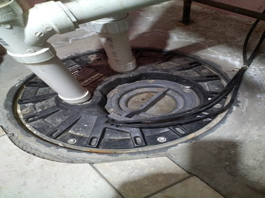
The Pump Station in the floor under
the Fresh Water Pressure Tank. |
||
|
||
|
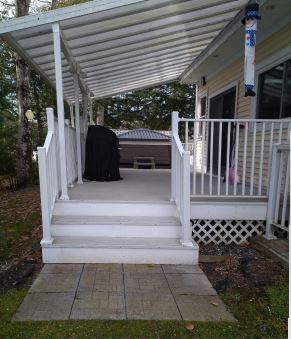
Septic
Tank Access The Paving Tiles at the base of the steps up to the covered deck are
directly over the pumpout access to the 1000 Galon concrete septic tank. Lift the first two rowes of tiles and then
lift the round concrete cover below the tiles and you will see the access
cover on the top of the inground Septic Tank. |
|
|
|
Septic Tank Access
Septic Tank Access; 2 |
||
4. Operation: Special use of The
Ground Floor Toilet
|
1. As the ground level toilet flushes
to a Pump Station: DO NOT FLUSH CARDBOARD, PLASTIC, RUBBER, OR STRING. 2. If this Bathroom is not used on a
regular basis add water to the drains once every season (every three months)
to compensate for evaporation of water from the drain traps. Full drain traps
provide a stop to odors. |
5. Maintenance:
|
1. Pump out the Septic Tank on a
regular schedule based upon occupancy or at least every three (3) years. |
6. Reference / Links:
Pat Jackson Septic Pumping
Website Phone: (207)
623-3223
7. Other:
Page File Information How to Edit the Pages of this
Guide
C:\Users\administrator.MAPLERIDGELIVE.001\OneDrive\1StWebsite\119MRD\Systems\Waste_Water_Septic_Plumbing_System\Waste_Water_Septic_Plumbing_System.htm
End of Page