119 Maple Ridge Drive,
Monmouth, Maine 04259-7334
Hosted By: mapleridgelive.com
Electrical System
|
Main Menu |
|
Select
the Page Menu for full access to all Electric System components.
Select this
symbol to return to the Main Menu. è Δ
Select this
symbol to return to the Page Menu. è <=
Electrical System Page Menu
Page Menu Main Menu
External
Electric Meter and Panels
200 Ampere Exterior Isolation
Panel and Standby Generator Bypass Switch
Standby
Generator Maintenance Schedule from The Operations Manuel
Standby Generator Operation Manual
Standby Generator Service Contact Information
200 Ampere Dual Main Circuit Panels #1 & #2
in the Garage
100 Amp Sub-Panel #1 in Garage on Circuit Breaker
# 5+7 of 200 Amp Master Panel #2
30 Ampere Sub-Panel #2 in Work Bay on Circuit Breaker
# 1+3 of 100 Amp Sub-Panel #1
Kitchen 40 Ampere Sub-Panel #3 on Circuit Breaker
# 17+19 of 100 Amp Sub-Panel #1
Note on Breaker 6B on the Kitchen Sub-Panel #3
Dead Kitchen Switch on Breaker 6B (Photo Image)
100 Ampere Sub-Panel #4 on the Deck under the Canopy
Hot Tub Disconnect on the Deck on 50 Amp Circuit
Barker # of 100 Amp Sub-Panel #3
|
Electric Power Sources: The home and
grounds are serviced by a 200 Ampere 110 / 220 Volts electric supply provided
by Central Maine Power or by a 100 Ampere 110 / 220 Volts Standby Generator Power Supply Description: The CMP 200
AMP Service via the Smart Meter and external Master Panel or the 100 Amp
supply from the Standby Kohler Generator enter the home at Master Panel #1 and Master
Panel #2 in the garage. These two
panels are tied together with 200 AMP Jumper cables to provide a total of 60
Primary Circuit Breakers (30 in each panel) to manage the Electrical Load. The load is
split further into 4 Sub-Panels from primary breakers on Master Panels #1
& #2 as diagramed below. These Sub-Panels provide more Circuits to manage
the load and put the control breakers close the circuits they manage. For
example, the Kitchen Lights and Power are mostly managed at the 40 AMP
Sub-Panel #3 in the Kitchen Pantry. This design adds
more control and circuits for more discrete distribution of the load without
bundling multiple circuits on a single breaker. It does also mean that you need to know how
the load is dispersed from the two Master Panels in the garage to primary
circuits and through the 4 Sub-Panels to secondary breakers in
each Sub-Panel. See the Panel Diagram. A dangerous
short circuit is protected by the Master Panel that supplies the power and
the Sub-Panel if the circuit is on one of the 4 Sub-Panels. In that case more than one breaker may need
to be reset after the issue is resolved. With over
100 circuit breakers the load is very discreetly delivered and there has
never been a “tripped breaker” due to overload since the system was
installed. Because of
the complexity of the Electric Power Distribution System this information is
provided for you or your electrician if you need to isolate a circuit for
modification or maintenance. For
example, to empty the Hot Tub you must shut down the Tub in its Disconnect
Panel or at its supply in the Sub-Panel #4. |
|
External
Electric and Communication Panels |
|
|

|
200 Ampere
Exterior Isolation Panel and Standby Generator Bypass Switch |
|
The 200 Ampere
Exterior Electric Isolation Panel is a system safety shutoff for interrupting
power from the CMP Meter Supply Panel.
The Standby
Generator Bypass Switch is activated when power is lost from the CMP Meter
Supply Panel. The activated Bypass Switch isolates the CMP Meter Supply Panel
from generator power blocking dangerous electrical back feed to the community
wide Power Grid. The activated Bypass
Switch starts the Standby Generator within five (5) seconds after loss of
power from the Grid. Note: if the Standby Generator is not “taken
offline” (turned off) when the 200 Ampere Breaker is shut off the Generator
Bypass Switch will engage, and the Standby Generator will start supplying
power to the entire home electrical system through the Dual Master Panels #1
and #2. To totally isolate
the entire system from both power sources, turn off the Standby Generator and
shut off the 100 Amp breaker on the generator and then turn off the 200
Ampere Breaker in the Exterior Electric Isolation Panel. |
Simplified Power
Supply Panel Diagram
|
Exterior Panels |
|||||
|
Generator Switch |
200 Amp Emergency Service Isolation Breaker |
CMP ç Smart Meter |
|||
|
↓ |
↓ |
|
|||
|
Main Panel #1 200
Amp Master Panel #1 100
Amp Breaker
# 27+28 ↓ |
Interior Panels ç200
Amp Jumper è |
Main Panel #2 200 Amp Master Panel #2 100 Amp Breaker # 5+7 ↓ |
|||
|
100
Amp Sub-Panel #4 On
the Deck 60
Amp Breaker ↓ |
|
100
Amp Sub-Panel #1 In
the Garage 30 Amp 40 Amp Breaker
# 1+3 Breaker # 17+19 ↓ ↓ |
|||
|
Hot
Tub Disconnect Panel 20-
& 30-Amp Breakers to Tub |
|
30
Amp Sub-Panel
#2 In the Work Bay |
40
Amp Sub-Panel
#3 In
Kitchen Pantry |
||
|
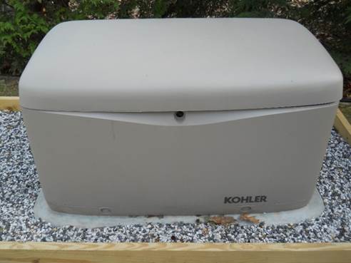
100 Ampere 220
Volt Standby Generator |
|
|
|
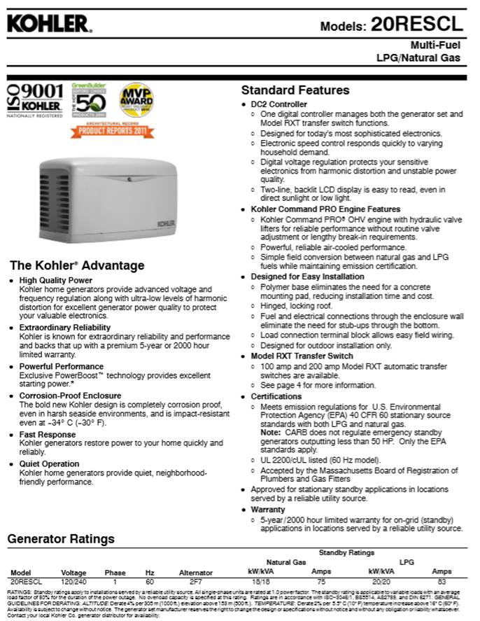
Generator
Specifications Sheet |
|
|
|
Standby
Generator Contact Information Kohler
Power Website (National site) Mid-Maine Generator (Installation
Dealer) 207-395-8066 1388 Route 202 Winthrop, ME 04364
4.55 mi. Email | Website | Directions Link to Generator Operation Manual |
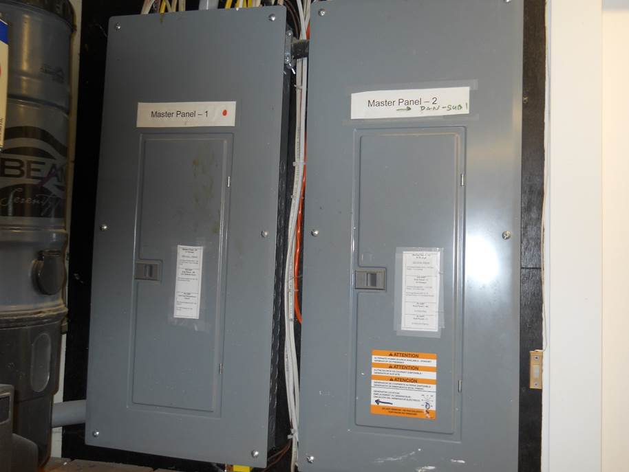
200 Ampere Dual
Main Circuit Panels #1 & #2 in the Garage
|
|
|
These two master
panels are connected in tandem with 200 Amp ‘Jumper Cables” and essentially
operate as a single Master Power Station.
All primary circuits and Sub-Panels and their circuits can be isolated
from these two panels. Each of these
panels have a 200 Amp Master Circuit Breaker. |
Master Panel #1
in Garage
|
Master Panel #1 in Garage 200 Ampere 110/220 Volts
|
Master Panel #2
in Garage
|
||||||||||||||||||||||||||||||||||||||||||||||||||||||||||||||||||||||||||||||||||||||||||||||||||||
|
Description 100
Amp Sub-Panel #1 in Garage on
Circuit Breaker # 5+7 of 200 Amp Master
Panel #2 |
|
This 100 Amp
Sub-Panel #1 is powered by the Master Panel #2 and feeds power to its
circuits and to the circuits on the 30 Amp Sub-Pane #2 in the Work / Storage
Bay and the 40 Amp Sub-Panel #3 in the Kitchen Pantry. |
|
|
|
|
|
|
|

|
Braker List for
the 100 Amp Sub-Panel #1 in Garage
with power from Circuit Breaker # 5+7 on 200 Amp Master
Panel #2 |
|
|
||||||||||||||||||||||||||||||||||||||||||||||||||||||||||||||||||||||||||||||||||||
30 Amp
Sub-Panel #2 in the Utility Bay
|
Δ Labels for the Breaker Panel in the Utility Bay Breaker list
for the 30 Ampere Sub-Panel #2 in Work Bay on
Circuit Breaker # 1+3 of 100 Amp Sub-Panel
#1 |
|||||||||||||||||||||||||||||||
|
|
|||||||||||||||||||||||||||||||
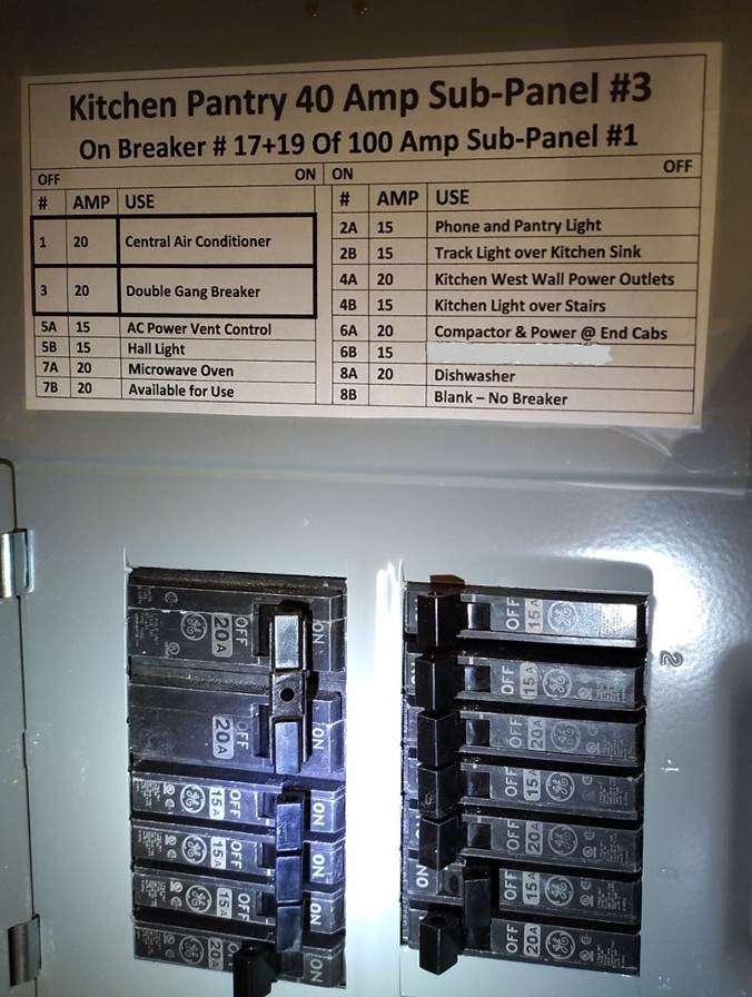
40 Ampere Sub-Panel #3 in Kitchen
Pantry
|
|
||||||||||||||||||||||||||||||||||||||||||||||||||||||||||||||||||||||||||||||||||||||||||||||||
|
Breaker List for: Kitchen Pantry 40 Amp Sub-Panel #3 See note on breaker 6B below
|
||||||||||||||||||||||||||||||||||||||||||||||||||||||||||||||||||||||||||||||||||||||||||||||||
|
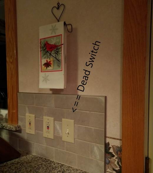
The Dead Kitchen Switch on Breaker 6B |
|
|
|
Note on Breaker
6B above: refers to this dead
(non-functioning) switch which supplies energy through Breaker 6B to a cable
behind the Trash Compactor to be accessed through the exterior wall to supply
supplemental lighting to the covered deck outside of the Kitchen Door. |
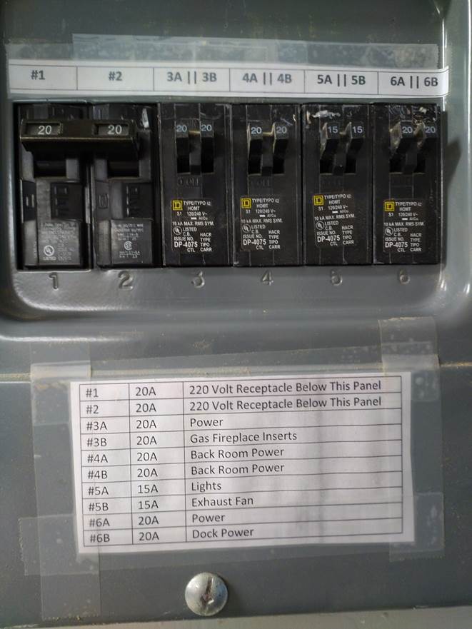
100 Ampere
Sub-Panel #4 on the Deck under the Canopy
100 Ampere
Sub-Panel #4 on the Deck under the Canopy
|
|||||||||||||||||||||||||

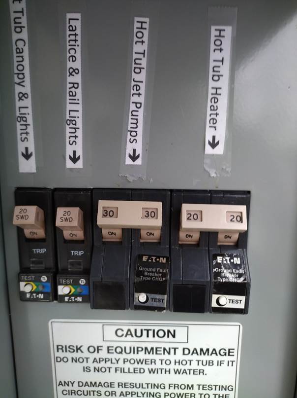
Hot Tub Disconnect on the Deck on 50
Amp Circuit Barker # of 100 Amp Sub-Panel #4
|
|||||||||||||||||
Hot Tub Disconnect on the Deck on 50 Amp
Circuit Barker # of 100 Amp Sub-Panel #4
|
|
|
The
Hot Tub Disconnect Panel is powered by the 60 Amp Breaker on the 100 Amp
Sub-Panel #4 and provides power to the Hot Tub Heater via its 20 Amp 250 Volt
GFI Breaker and to the Hot Tub Pumps via it 30 Amp 250ilter Volt GFI Breaker. References: The State of Maine had adopted the 2020 National Electric Code (NEC) for all new construction. Page File Location:
End of Page |
|
|
|