|
|
|
Owners Guide – 119 Maple Ridge Drive,
Monmouth, ME Lake
Water Irrigation System Information: Hydrants,
Sprinklers, Irrigators, and Drains Hosted by: mapleridgelive.com Select
this symbol to return to the top of this Menu. ---> Δ Lake
Water Pump System Page Menu Lake Water Pump System
Procedures Lake Water System Components Index Information: Lot #95 at 119 Maple Ridge Drive is
set up with a substantial Lake Water Irrigation System with
Garden Hose Connection Hydrants, ten (10) Sprinklers, two (2) Irrigators and
six (6) low point Drains. CAUTION:
be advised that THE UNTREATED LAKE WATER SUPPLIED BY THE IRRIGATION SYSTEM IS
NOT SAFE FOR DRINKING. It is suitable
for external personal hygiene. There
is drinkable well water available at the hydrant at the RV
Pad. Lake
Water Irrigation System Components Menu Lake
Water Pump Lake Water Expansion Tank and Pressure
Switch Drains Irrigators Sprinklers Hose
Connector Hydrants Foot
Wash Stations Pressurize the System The
Lake Water Irrigation System is built up on two major components: The Lake Water Pump and The Pressure Control Switch at The
Expansion Tank. These two (2)
components produce and control a high volume of pressurized supply of Lake
Water to all other system components. Other System Components Drains: Important Note: All Drains must be closed to pressurize
the system! There are seven (7) Lake Water Irrigation System Drains used
for winterizing (Draining) the system.
See “The Lake Water Winterization Procedure”. Important Note: the first two Drains on this list are internal drains
and must be closed if the pump is energized to pressurize the system or
internal flooding in the home will occur. 1.
Large Drains in the “Pit” at the entrance to The Work / Storage Bay 2.
The Pressure Tank Drain at the back of
The Work / Storage Bay 3.
The small Waterfront Drain just below the Hydrant and Electric Post at the Dock Access. 4.
The Large Waterfront Drain is located just above the Waterfront Rock
Wall between the Dock Access and the Boat Launch. 5.
The Drain in the “Pit” below the Hydrant and Electric Post at the side
of the driveway forward of the entryway to the home. 6.
The Drain at the Northeast side of the lot at the edge of the wet land. 7.
The Drain at the Northeast corner of the lot just behind the Access to
“Little Hook” (this drain is at the bottom of an access pipe and needs to be
operated with The Extended Valve Key kept at that location. Irrigators: ·
The two (2) Irrigators o
The North Rose Hedge Irrigator o
The South boundary Tree Line Irrigator Sprinklers: ·
The Eleven (11) Sprinklers o
The two (2) North Rose Hedge Sprinklers o
The four (4) West Boundary Line Sprinklers o
The three (3) East Boundary Line Sprinklers o
The Sprinkler at the access to “Little Hook” o
The Mobile Tripod Sprinkler Foot Wash Stations: ·
The Two (2) Foot Wash Stations o
Located at the corner of The Overhead Door to the Work
/ Storage Bay o
Located on the Deck at the back corner of The Hot Tub Hose Connection Hydrants: ·
The thirteen (13) Lake Water Garden Hose Connection Hydrants o
The Garden Hose Connection Hydrant at the Lake Water Expansion Tank and
Pressure Switch. o
The Garden Hose Connection Hydrant at the East side of the Overhead
Door to the Work / Storage Bay. o
The Garden Hose Connection Hydrant at the Hydrant and Electric Post at
the Dock Access. o
The Garden Hose Connection Hydrant Just North of the Flagpole and just
east of The Well. o
The Garden Hose Connection Hydrant at the Northeast side of the lot at
the edge of the wet land. o
The Garden Hose Connection Hydrant at the access way to “Little Hook” o
The Garden Hose Connection Hydrant at the on “Little Hook”. o
The Garden Hose Connection Hydrant at the South side of the Large
Sheed. o
The Garden Hose Connection Hydrant at the Hydrant and Electric Post at
the side of the driveway forward of the entryway to the home. o
The Garden Hose Connection Hydrant at the Southeast corner of the lot
at the Lamppost. o
The Garden Hose Connection Hydrant at the Southeast corner of The Deck. o
The Garden Hose Connection
Hydrant at the Southwest corner of The Deck. o
The Garden Hose Connection Hydrant at the Northeast corner of the home
below The Deck. Photos
/ Graphics: See
the Lake Water Pump System Components
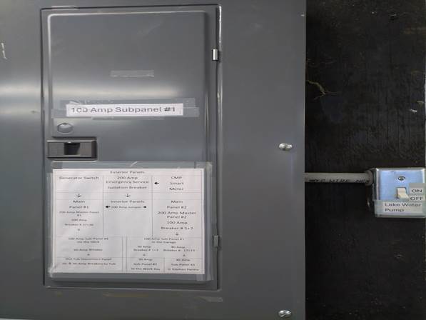
Index for visual ques on individual component locations. Operation: To
pressurize the Lake Water Pump System,
locate the Lake Water Pump Switch to the right of Electric Subpanel One (1)
in the garage and set the switch to the on position. The system will come up
to sixty (60) pounds of pressure within a minute by putting available Lake
Water at each of the Irrigators, Sprinklers, or hose connectors, (Hydrants).
Access water usage at each component by opening its valve to release the
water. The
pump is capable of supplying water at sufficient pressure and volume to
actuate four (4) sprinklers simultaneously. Maintenance: See
the Lake
Water Pump System Procedures Reference
/ Links: Δ Lake Water Pump System Components Index Lake
Water Irrigation System Individual Components Lake
Water Pump The Lake Water Pump is a one-half Horsepower (1/2 HP),
two hundred twenty-volt (220 V), submersible well pump. The Lake Water Pump is energized by the
#10 and #12 two hundred twenty-volt (220 V) Circuit Breaker on Subpanel One
in the Garage with its Control Switch mounted just right of The Pannel. The 220 V power cable passes from Subpanel One in the
garage to the space above the closets on the South Foundation Wall and
connects at a junction box on the East wall, back corner of the Work /
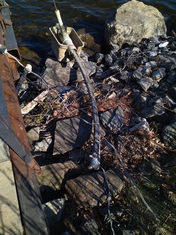
Storage Bay. When the system is pressurized by
activating The Lake Water Pump Switch to the right of Sub-Panel One, the pump
supplies a high volume of lake water at thirty to sixty pounds of pressure
(30 – 60 PSI) via “The Lake Water Main Supply Line” located at the East side
of the “Dock Access Point” shown below. The Lake Water Main Supply Line connects to
all Hose Hydrants, Sprinklers, Irrigators and “Low Point Drains” via manual
valves to control the flow of water to intended components. Important Note: ·
Large Drains in the “Pit” at the entrance to The Work / Storage Bay ·
The Pressure Tank Drain at the back of The Work / Storage Bay are
internal drains and must be closed if the pump is energized to pressurize the
system or internal flooding in the home will occur. The two hundred twenty-volt (220 V)
“Double” Circuit Breaker #10 and #12 on Subpanel One in the Garage energize
The Lake Water Irrigation System Pump Control Switch mounted just right of
The Pannel. With all Drains closed this switch
pressurizes the system. Subpanel One in the Garage with The Lake Water Pump
Switch on the Right
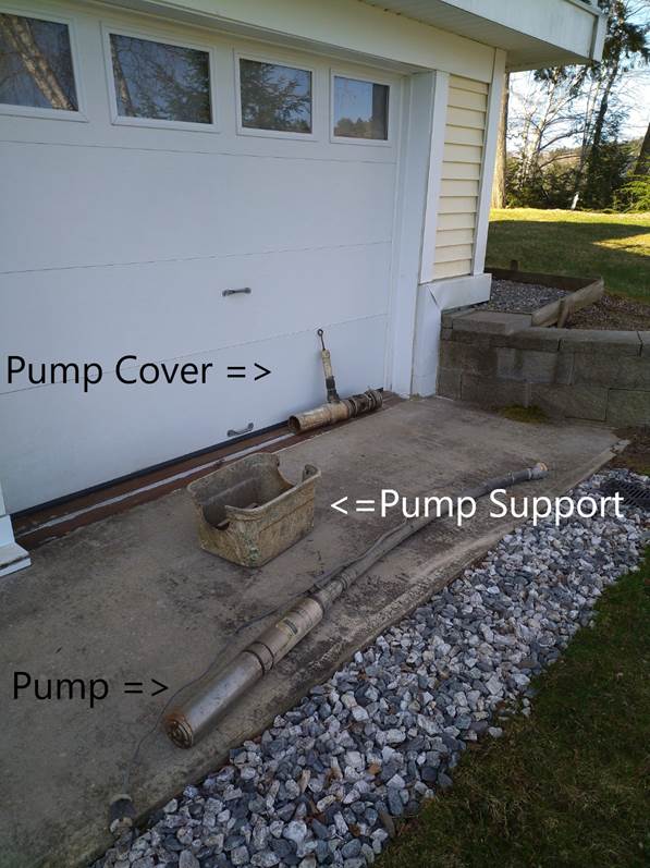
The Lake Water Pump Assembly componants shown below include The Pump and, The
Pump Cover with its screened intakes to filter out debris and its support
“eyelet” to aid in positioning the pump in the water, and The Pump Support
to keep The Assembly off of the lake bottom. See The Views that shows the
individual componants and The Lake Water Pump Assembly componants together as
a unit.
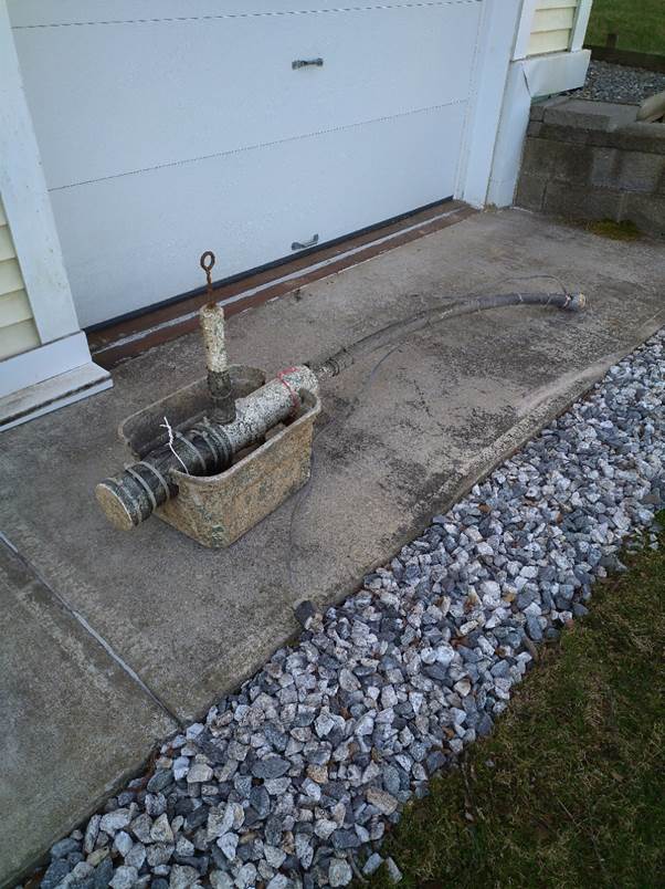
The Pump slides into the
“Cover” with filter screen to keep out debris and the Pump and Cover sit in
the Support Cady as seen in this view.
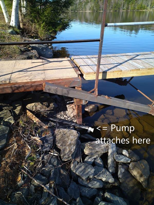
Dock
Access Point with The Connection to the Lake Water Main Supply Line.
The
Pump Assembly is positioned at The Main Lake Water Supply Line at the base of the
dock access point shown in the next views and
is ready to slide into the water of the lake.
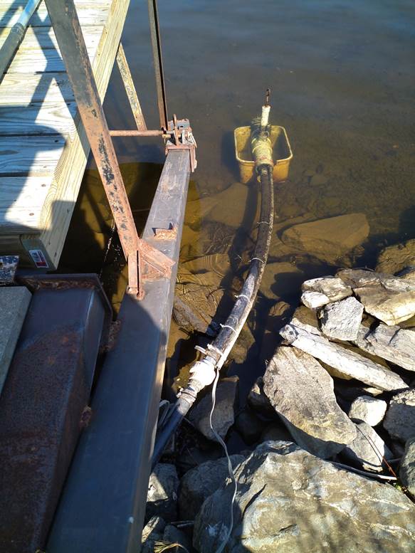
The Pump
Assembly is positioned in the water and ready to be energized aftrer pluged
into the 220 volit receptical on the utility post at the dock access pont. Note: do not pressurize
the system before closing all Drains.
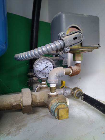
Lake Water Expansion Tank and Pressure Switch The Lake Water Pump Pressure Switch controls energy to the pump that
pressurizes The Expansion Tank to stabilize the system pressure to all
components while the pump is cycled “on and off” by The Pump Pressure Switch
to maintain water pressure between thirty and sixty pounds of pressure (30 –
60 PSI).
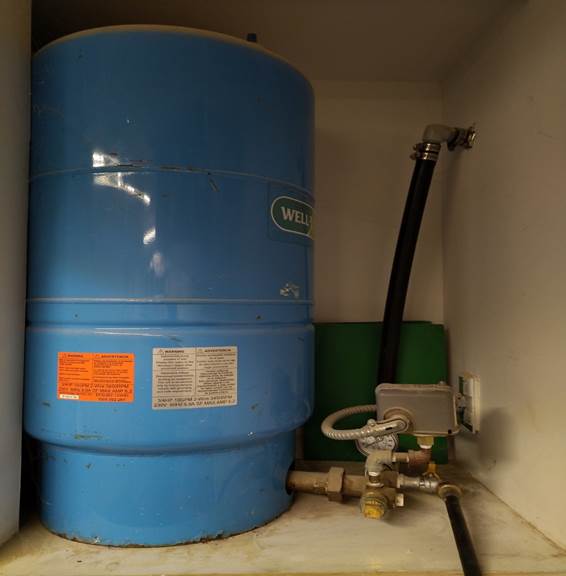
Lake Water Expansion Tank stabilizes the system pressure to
all components while the pump is cycled “on and off” by The Pump Pressure
Switch to maintain water pressure between thirty and sixty pounds of pressure
(30 – 60 PSI).
The Lake Water Pressure Tank with
Drain The Lake Water Pump Expansion Tank
is located in the back of The Work / Storage Bay, and it has a drain valve
that must be closed when pressurizing the system or significant flooding will
occur. Lake Water Pump Power Cable Junction
Box at the back of the Work /Storage Bay How
to Edit the Pages of this Guide Page
File Information: G:\mapleridgelive\119MRD_WS\Grounds_Exterior_Features\Lake
Water Pump System for Hydrants, Sprinklers, and Irrigators\Lake Water Pump
System Information.htm |
End of Page